
Intrepid Solar, Part Deux

Have Space, Will Travel. This rack carries two framed solar panels, resting on their sides.
Stowing one framed solar ground panel aboard the Four Wheel Grandby is an easy matter. It’s merely a matter of affixing a couple of aluminum angles and wood slats to the bottom of the bed overhang, above the truck’s cab. For a workable presentation of the details, head for Two Happy Campers. Doubling the number of panels presents a clearance problem, however. The panels I have are a bit too wide to fit side-by-side, so that’s out. There’s enough room under there for just about any size of single panel you might care to heft, though higher weights mean you need to pay more attention to exactly how those slide rails are attached to the surface above. As far as clearance goes, there’s plenty available. The combination of the camper’s comparatively light weight and the F-250’s frame strength simply won’t allow the panel-to-roof gap to close much. I wouldn’t expect roof contact during slow off-road articulation either, since the Ford’s roof is curved and negates much of the effect of frame twist in closing up clearances to the hanging panel.
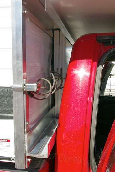
So that’s the “traditional” external storage solution. I opted for an alternate approach: a rack mounted to the Grandby’s jack mounts, which holds the twin panels upright. In practice, it’s a very tight squeeze, and care must be taken to keep any slide rails clear of both the camper’s front window and the rear sheet metal of the truck cab. Fortunately, this is correctable by backing the camper up enough to insert a thin spacer in front of the rubber bumpers it uses to space itself away from the front of the truck bed. Then move it forward again and readjust the turnbuckles for tightness. I’ll be checking clearances over time to look for indications that this needs to be done – the Ford’s frame is not exactly a wet noodle, but I’m more interested in how it reacts in twist.
Since the looming deadline for departure made this pretty much of a one-shot deal for me, there are a couple of details I’d do differently, and I’ll share them here. Apart from those, I was surprised as anyone when the darned thing went together, fit in the space, and now actually seems to work. Getting accurate measurements of the area I had to work within was a sloppy affair. There are several possible approaches to storing the solar ground panels in this way. My own preference was to keep it all in the family, so to speak. Support the spare panels entirely within one structure which is tied only to the truck bed, or to the camper, but not both. The Grandby’s jack mounts serve as an inviting mounting point, since they are designed to support a large portion of the camper’s weight. It was very tempting to split duties between a main rail on the jack mounts and an independent top rail tied to the bed overhang, but I obviously made my choice and developed it. Although I don’t plan on removing the Grandby anytime this century, the panel rack is removable to allow lift jacks to be mounted, if needed.
My Granby’s jack mounts are steel (with rust-free aluminum mounts being an additional $100). The rack itself is all-aluminum to save weight and ease fabrication. By description, it basically consists of two thick (1/4″) L-angle uprights, one on each jack mount. These uprights could have been mere flat plates to do the same job, but that starts to get into flex issues, and that’s not good for aluminum. A 1/4″ flat plate is mounted to front of these to serve as a spacer, necessary to get the main panel-carrying crossmember clear of the front window gasket. That crossmember is a 3′ x 3″ x 84″ L-angle, 3/16″ thick. It does all the work, basically, holding the weight of the panels. A thinwall L-angle is mounted at the top of the verticals in order to form a movement-limiting sleeve to help lock in the panels. An additional thinwall L-angle is mounted to the front of each, so that the effect is similar to a couple of C-channels facing each other. The upper structure serves mainly to keep the panels from flopping forward or rearward, and these forces are pretty minor. The thick L-angle in the lower structure obviously does the yeoman’s work here, the thinwall L added in front having little to do but keep the panels off the truck’s rear window surround.

It begins here, at the jack mounts. An L-angle upright is bolted to each one.
The methods of fastening vary. I used stainless steel bolts and locknuts where possible. The lightly-loaded thinwall L’s that keep the panels from moving forward are retained with a form of VHB tape called 3M Extreme Strength Outdoor Mounting Tape available at big box home improvement stores. It’ll hold for this job. Unless I was willing to drill a new 3/8″ hole through a half-inch of aluminum and steel – which I wasn’t – welding the main crossmember to the upright spacers became the only option. Twenty dollars and a trip to Beck’s Performance in Yuma was all it took to get it welded up with a minimum of warping. When he was done, all the holes still lined up perfectly with the jack plate holes, and it won’t be stress-cracking anytime soon even if the front wall of the camper flexes, which it may. For a mere forty-pound load, I think suspect it’s stronger than it needs to be. That’s good, but not entirely good.
Although the rack carries two panels, it’s not rigged as a true twin-track slider. I’ve arranged rubber stops in the track such that the first panel is inserted forward, and then pushed back into a sort of retaining cubby. The second panel is then inserted in front of it. Thanks to the upper structure, a trip through the nasties does not allow the panels to bounce up and over any stops – there simply isn’t the physical room to do so. A lowered stop on the forward track of the driver’s side allows that panel to be lifted slightly and pulled out. Removal is only possible from the driver’s side. It’s unlikely to hop out on its own, and this is made more than unlikely by a coiled aircraft cable on the other end of the panels, which constantly yanks them toward the passenger side stops. Combined with a padlock going through one of the jack plate holes, that cable also serves as the anti-theft device. It’s far from being a theft-proof system, but should deter impulse or “unprepared” theft such as can be found in most short-term parking. The panel handle fasteners are not accessible when the panels are inserted back-to-back, and this positioning also affords more weather protection to the panel wires and junction boxes.
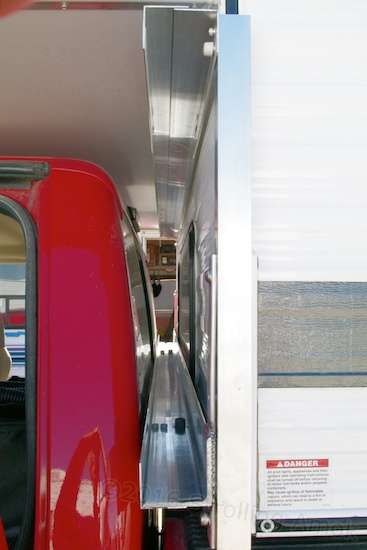
This is what the solar panels see before sliding in. Each panel must be inserted in the forward track, over the lower button. The UHMWPE tape that eliminates sliding friction is clear and difficult to discern here. A third bolt at the center of the jack plate has not yet been installed, but what you see here is basically it. Rail clearance to the truck cab is a mere 1/8″ on this side, and 1/16″ on the other!
Once one end of the coiled cable is slipped out of the panel handles on the passenger side, pulling them out is a cinch because of thin adhesive-backed UHMWPE (ultra-high molecular weight polyethylene) tape laid down along the main crossmember. Combined with drawer handles on the solar panel frames, inserting and removing the panels really is pretty painless, and greatly slows the wear and tear caused by aluminum parts sliding against each other. This tape was also placed forward and back within the upper structure’s “C”, since there was room for it. Obviously, none is needed above the panels.
Besides the too-close clearance between the main crossmember and the rear of the truck cab, there are a few issues that work brilliantly now, but may pose deterioration issues in a year or less. The off-the-shelf UHMWPE tape is not UV resistant. That option is available for huge custom product runs, but it’s not stocked anywhere I could find. The panels protect whatever is underneath them, but my concern is for the more exposed driver’s side slide-out. The rubber stops, pack-ratted from numerous Chicago industrial shows decades ago, may also suffer in a few years. Fortunately, they’re tucked in there a ways, so that should be a little slower, and there are alternatives available.
A bike cable keeps tension on the panels, though an appropriate-length straight cable would do just as well. I already had this one. Tapes are unnecessary on this end of the rail, but the rail was prepped before the stop system was improvised.
The most problematic error I made was to panic and lean toward “structural” aluminum, which is twice as strong as its “architectural” alternative. But despite concerns about 40 pounds bouncing around on a very stiff suspension, the real problem wound out to be not alloys or strength for the loading of this long span, it was the extrusion’s profile. Structural aluminum is the less expensive of the two, and has a rounded fillet where the two walls meet. It’s a rounded corner, but the solar panel edges are squared off. This is of no concern when the floor of the lower structure is sloppy with space and more than wide enough to take both panels, which stay down on the flats. In my situation, the gap between the truck’s cab and the camper front wall was just as tight as I’d feared. There’s no space to spare, and the fabricated C-channel must be as narrow as possible. That small fillet on the structural aluminum beam suddenly became a big deal when it acted like a wedge and jammed the rear panels together firmly enough to make panel insertion and removal a battle.

This rail was the first crossmember to be fitted, so I just stayed with bolts in case of unexpected problems. I would have preferred true C-channels top and bottom, but none were quite wide enough, so I had to roll my own.
What I should have done is bite the bullet and use the square-cornered architectural profile, making the full width of the channel floor available. Too late now! The make-do remedy was to raise the rear panel above the fillet by adding a length of foam 3M VHB tape on top of the UHMWPE track, and put one more layer of track on top of that. Presto, no more jamming. Since the protruding heads of fasteners also became an issue with the narrow channel, potentially interfering with the rear panel withdrawal, it became clear that welding the main rail to the uprights would be necessary. In the original concept, the short spacer uprights were tucked out of sight behind the L-angle uprights, giving a much cleaner appearance overall. Once permanent welding came into the picture, it became clear that such an arrangement could not be removed again without shoving the camper back to get enough clearance to pull the assembly out. Not the best. The vertical spacers would need to be placed in front of the long uprights and the main crossmember welded to them instead. Since all holes were drilled for the original clean upright arrangement, the resulting change in appearance isn’t too good, but hey, it works.

Each panel has simple handles top and bottom. Velcro industrial adhesive tape is used to keep cables tucked away, the outside piece adhering to Saran Wrap so it stays clean. Each has a folded-over “handle” to ease removal.
If I had to do it over again, I’d opt for that main L-angle to be square-cornered architectural aluminum, as well as having a thinner 1/8″ wall thickness. That would be a gamble that might possibly allow sagging or twist over time, but it would be worth trying. Since the FWC itself is actually designed to allow some “reed in the wind” twist, then adding a stout stiffener tying the front jack mounts together, as I have, may not be the best way to go. Likewise, the two L-angle uprights are unnecessarily strong, but since they also act as spacers to help shove the main crossrail forward and away from the camper’s window, there’s no big advantage in thinning them. Like the rest of the camper, the parts should only be as strong as they needs to be, and no more. But, I was a product designer, which is not the same thing as being an engineer. I can solve problems, but not quantify or optimize the solutions except by actual hands-on testing – in this case, with my own money, which is much spookier than spending a client’s! I’d also take more time to address the relatively limited lifespan presented by the rubber stops (like locating urethane equivalents), and finding alternatives to the unprotected UHMWPE tape. But, this rack represents a workable start based only on rudimentary planning. The remainder was improvised, but I can recommend it as an approach worth considering. Admittedly, it’s much more expensive than the usual underbed sliders and ties up the forward jack mounts, but it’s a good way to handle a lot of weight on a stiffly-suspended vehicle, and in a way that doesn’t carve up the camper to do so. The Intrepid’s solar is now complete!
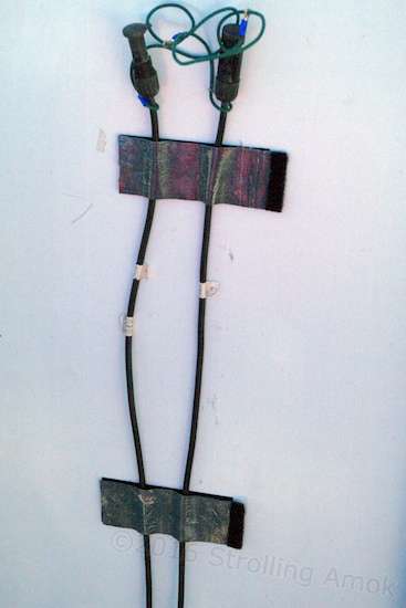
This utter brilliance is marred by the detail that the Velcro’s adhesive is having trouble sticking to the white plastic backing on the solar panel. I’d guess that I have about a week to come up with a Plan B here. MC4 connectors are about as touchy as they get for this type of usage, so sealing caps are highly recommended.
One last caveat: FWC appears to tailor front bed bumpers based on the vehicle they are intended to be installed in. I’ve seen a Dodge/Grandby setup that provided just oodles of rack space, while mine for the Mighty Furd is a “normal” close fit. If you’re going to attempt this approach for twin panel storage, either work out the stacking space you have very carefully, or select shorter panels that can be stored inline along a single, narrower track.

HOLY CRAP, what a project! Congratulations on having the determination and mental bandwidth to make this wizard solution work. Respect!
Thanks, Rod! Considering that I usually don’t know what day of the week it is and can’t possibly remember more than two items on a mental shopping list, it’s an accomplishment that I’m glad is over and done with. I’d rather be goofing off and frittering away precious time!
wow, that is quite the accomplishment! Very clever problem solving. Are you concerned at all about the small clearance between your mounts and the cab of your truck with rough ground flexing?
Oh sure! But all I can do is find a decent spot out here to get the twist going stoutly in each direction, park in the max twist, then get out and take a look. In general driving I generally take it easy behind the wheel, so about all I can do is occasionally look for early signs of contact due to straight-up flex. There are a few highway/Interstate overpasses in New Mexico that might help with that, and a few RR crossings in Illinois! I’m not really interested in attempting to force contact that would not normally occur where and how I go. It’s not like I’m signing this off for production, so I won’t be hot to scramble the camper’s contents. I’m just fortunate that the “fix” is pretty straightforward, though I’m not expecting that it will be necessary.
yes, it’s good that it would be easy to fix. Do you mind losing the view out the back? Do you use a camera and do people use their rear cams full time when they don’t have a back window?
Being short and not getting any younger, I appreciate the fact that you won’t have to reach overhead to wrestle heavy panels down from up high.
The view to the rear is already so slot-like through the center of the camper that it’s pretty much relegated to a yes or no vision of a vehicle directly to the rear, which is only really useful backing out of parking spaces in mall parking lots. To me, it’s no great loss in functionality to have the solar panels blocking it off. I have no idea whether people use rear cameras while driving, Ming. Seems like it would be handy, and most applicable for big and wide motorhomes. My side mirrors can stand out there enough to get a pretty good view of what’s back there. I do have a simple magnet-mount wireless camera that I’ve used to greatly speed up the hitching of the Defiant, but it’s wanting as a driving aid because of the limited battery run-time. It’s now also problematic for mounting since nearly all of what’s back there now is aluminum or plastic! It can be done, but I’m not going to press for it now until I get some indication that it’s needed.
And you’re right, heavy and high do start to weigh in as more of an issue as age comes into play. And it’s not helped by the higher profile of modern “non-Jeep” 4WD vehicles. The rear rack setup puts the solar panel handles about at shoulder height for a straight pull, and they don’t “fall out” until they’re nearly all the way out of the track. They can be stalled at any point to allow changing stance or grip with each hand. At less than twenty pounds each in my case, it’s easy at this point.
Doug…just another one of your ideas that have left me thinking….’now why didn’t I think of that’. I don’t have the luxury of square corners, however I will have around 6 inches easy between cab and camper, so I am thinking of getting a ‘stand alone’ rack built, that bolts to the bed of the truck as I will have to support the top C channel.
My other option is under one the overhanging wings. They would extend no further out than the Jacks (or my dully fenders).
thanks for the inspiration.
Thanks, David! Without those corner-mounted jack mounts, there’s no particular need to have the rack come all the way out to the full width of the camper. The panels certainly don’t need the extra track length – they’re lost in there. I’d think if you can work out a decent bed mount rack, you might not even notice that storage at first blush. Have fun hashing something out!
From the pictures it looks like the lower Chanel is touching or very close to the cab . Did you drive it this way? Did the paint get scraped off from the frame flexing?
Welcome! Yes, I did drive it, expressly to see if and how the gap would change. After all, the ground panel rack was worked out after the camper was already installed, since I had no wild idea what kind of space I’d have available to me for the pre-existing panels. Let’s say there was a bit of “aggressive buffing” on the right side. A later article describes the insertion of a couple of common UHMWPE (white polyethylene) bread boards in front of the camper bed bumpers in order keep the camper back and gain a little more space. I had picked those up at a grocery store. A bit of touch-up paint did the trick on the cab. There isn’t actually much front-to-back bed movement going on with my truck. The paint wear appeared to be from the dynamics of twist, because I could park it on a diagonal ridge, get out, and look at what happened to the gap. Had I purchased new solar ground panels having thinner frames, the rack could have taken up less space and no camper reset would have been necessary.